A brief introduction
In instrumentation engineering, hydraulic system serves as backbone power for hydraulic actuators for valves (mostly on/off , shutdown valves, but there are control valves with hydraulic actuators as well). For offshore platforms, hydraulic system is a critical element of wellhead control panel (WHCP), provide power to open, close wellhead valves without any electrical power (from black start / start up without power).
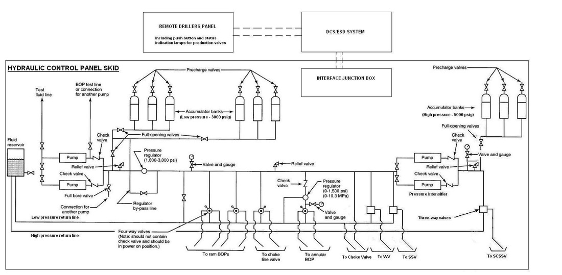
Schematic for a hydraulic system for drilling rig with extension to a small offshore mobile production unit
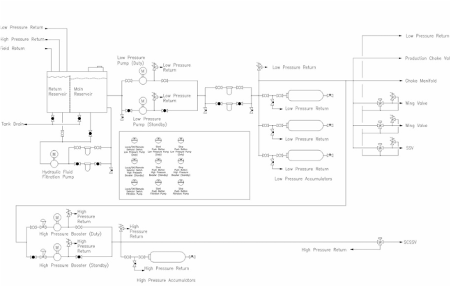
A typical Wellhead control panel (WHCP).
Normally for this system, we need to take special care for sizing of this particular item:
- Accumulators : to store the charged hydraulic fluid. During black start, the power comes from these accumulators
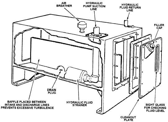
- Hydraulic Reservoir : to store all the supply / returned hydraulic fluid after use. Some reservoirs include a filtering system to reuse most of returned fluid.
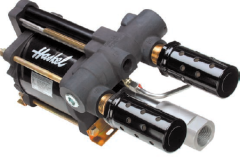
- Hydraulic pump: To charge the accumulator after the electric power is started. In the very unlikely case that the accumulators are empty and no electric power, a pneumatic pump with nitrogen tank are employed to charge the accumulator. All these pumps need to be sized accordingly.
Sizing for accumulator
The accumulator normally consists of 2 pressurized-linked chamber : one for charged gas (most of the time is Nitrogen N2) and one for charged fluid (hydraulic fluid).
As previously discussed, the accumulators are connected to hydraulic system (see the schematic above) and maintain the overall pressure for hydraulic system. Charged gas serves as a pneumatic "spring", slowly release its pressure via assumed ADIABATIC expansion (more to this in the formulator).
While most accumulators have designed volume (say, 12, 24, 37, 50L), due to minimum and maximum pressure of adiabatic expansion, only a smaller volume can be used to actuate the valves. It's typical for 50L low pressure accumulator to supply for 8L swept volume.
Some process inputs are required here:
The calculation is actually pretty simple:
This formula can be derived from adiabatic expansion (WIKI) . 0.7143 is a constant for nitrogen.
SAMPLE CALCULATION
As previously discussed, the accumulators are connected to hydraulic system (see the schematic above) and maintain the overall pressure for hydraulic system. Charged gas serves as a pneumatic "spring", slowly release its pressure via assumed ADIABATIC expansion (more to this in the formulator).
While most accumulators have designed volume (say, 12, 24, 37, 50L), due to minimum and maximum pressure of adiabatic expansion, only a smaller volume can be used to actuate the valves. It's typical for 50L low pressure accumulator to supply for 8L swept volume.
Some process inputs are required here:
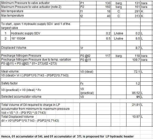
- Minimum pressure to valve actuator (P1) : when the valve actuators are sized, a minimum hydraulic pressure is required to check the torque of the actuator. This should be defined in specification for hydraulic system. For a low pressure system (LP), 120-130 barg is commonly used. For High pressure system, 180-190 barg is commonly used. At this pressure , the hydraulic pump will start.
- Maximum pressure to valve actuator (P2): when the valve actuators are sized, a maximum hydraulic pressure is required to check the rating. This should be defined in specification for hydraulic system. For a low pressure system (LP), 170-190 barg (2500-2600 psi) is commonly used. For High pressure system, 210-220 barg (3000psi) is commonly used. At this pressure , the hydraulic pump will stop. This maximum pressure might be lowered during operation, as one of our clients noted that at 186 barg setting, their tubing system and the actuators start to leak.
- Minimum outdoor temperature (T1)
- Maximum outdoor temperature (T2): temperature will affect the charged nitrogen pressure
- Displaced volume (Vr) : the volume of all the valve required to be actuated during black start. For a wellhead platform, normally you need to open 2 wells, which include 2 HP sub surface (SCSSV), 2 LP subsurface (SSV), 4 wing valves (WV), 2 choke valves, and some directing valves. A typical volume of 40-50L is normally considered
The calculation is actually pretty simple:
- Calculate actual pre-charged gas pressure due to temperature variation: precharged gas (nitrogen) are normally supplied with fix pressure (P0) (we used 117 barg / 118bara). Due to temperature variation, we must assume that the gas would be charged at highest temperature and used at lowest temperature. Therefore:
- Calculate the ideal volume of the accumulator:
This formula can be derived from adiabatic expansion (WIKI) . 0.7143 is a constant for nitrogen.
- Calculate the practical volume of the accumulator:
SAMPLE CALCULATION
Things to note: the higher the spread of max - min pressure, the smaller the accumulator system can be. However, higher max pressure can lead to leaking, and low min pressure can lead to huge valve actuator (this is serious for big high-rating valves).
Sizing for Reservoir (Supply / Return)
It's one of the easiest yet most tedious part of the sizing. To find the required volume of the supply reservoir, we need to know the total swept volume of ALL hydraulic user, including accumulators (that's why in the previous calculation, I purposely included the Total volume of oil required to charge the accumulator. This data is normally included in vendor's data for valve / valve actuators. It's really troublesome to find these information, especially in big projects. Do take in account for future valves as well, as modification of hydraulic system is normally discouraged. Bigger is better.
After all the hydraulic swept volumes are computed, we just need to take 200-300% extra for the ideal volume of the supply tank. This should be specified in specification for hydraulic system / specification for wellhead control panel. Round up the volume, and voila, we have the supply tank volume requirement.
The return tank is normally sized for all swept volume return, so just take all swept volume return, round it up and try to match it with the sizing of the supply tank (so we can join them together easily).
Sizing for Pumps
Pump need to be sized base on how long the pump need to charge all the accumulator from blank to maximum pressure.
Typically, 15-30 minutes is required for electrical pump and 5 minutes for pneumatic pump. This should be stated in specification for hydraulic system / wellhead control panel
The hydraulic fluid volume to be charged from blank to maximum pressure should be computed from accumulator calculation as dV = V0*((P0/P1)^0.7134 - (P0/P2)^0.7143)
Do note the maximum pressure required, as the higher the different pressure, the lower the pump capacity. You should check the pump chart for choosing the pump for hydraulic system.
Simple sizing formula for electric pump:
Pump rate = Hydraulic Power in kW * 600 / (Max pressure in barg)
Some tips
As engineer for hydraulic system package, I have noted some points:
- The higher the spread of max - min pressure, the smaller the accumulator system can be. However, higher max pressure can lead to leaking, and low min pressure can lead to huge valve actuator (this is serious for big size high-rating valves)
- The LP and HP hydraulic system can be jointed together, as HP take supplies from LP header. You need to pay attention to volume required for LP accumulator and supply tank.
- The actual calculation is pretty simple, but great care need to be done for compilation of data. Logical and simple compromises might lead to great saving.
- Never, ever put a shutdown valve in the hydraulic return. The fluid won't return when the system shutdown if that valve is closed/ faulty, thus render the whole system useless.
 RSS Feed
